Final Project
Showcase
First to showcase are the buttons- top button for volume up, bottom button for volume down, middle button for push to talk, and both volumes for play/pause.
featuring my excellent music taste.
The first video shows the volume controls. For the push to talk video, this is on a Discord call, so the green circle indicates that it's receiving the push-to-talk signal. The last video has the Spotify play bar at the bottom of the screen so you can see that it's actually playing/pausing. I think this is the weakest part of the project- it's really difficult to not also adjust the volume, and requires two hands. But hey, this's why we make prototypes.
Next is the indicator light. It flashes quickly while searching for a Bluetooth connection, blinks slowly when on, and holds bright when push to talk is active. (I changed how I wanted the LED to work after I filmed the button videos so there is a slight lack of consistency there, sorry~!)
featuring airplane turbulence shaking my camera.
The first video shows the quick flash searching indicator. The second video is the slow blink - it looks less but still a little bit choppy in real life. The stepping is due to the board's PWM only accepting integer values. The last video is the brightness when you hold down the push to talk button. I will never accidentally push it without realizing and then say something embarassing, which is a core fear of mine, because this light is very bright.
Process and Documentation
I got COVID-19 right at the end of the semester, and had to isolate in my room during a significant portion of the time I had planned to work on this project. As such, I wasn't able to make it as good as I wanted to, and am finishing writing this documentation on a plane home with terrible terrible United wifi- but! I still did a lot of work and learning, and I'm pretty happy with what I've made as a prototype.
This documentation is in chronological order, and includes ideas and messiness that didn't make it into the final version of the project.
See my final project proposal page.
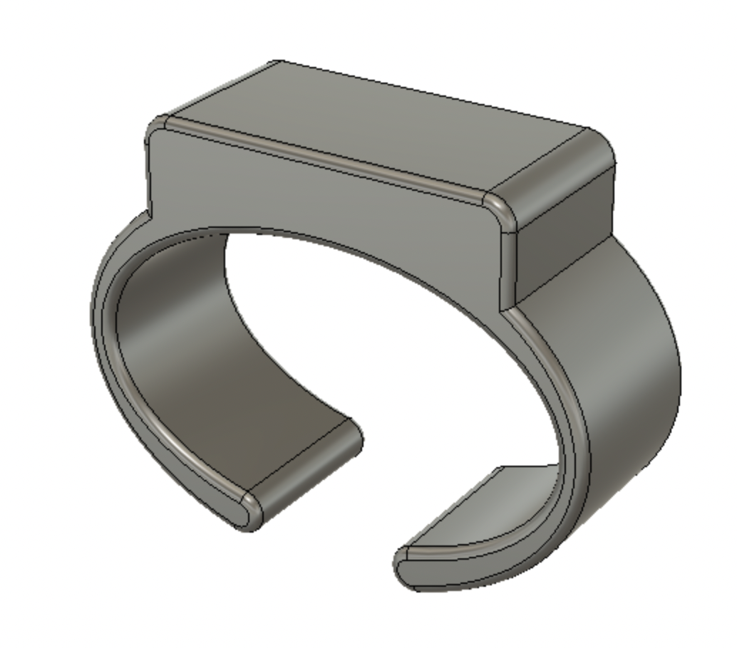
Here's an idea for a bracelet version. It's extremely preliminary because the most important thing is fitting all the electronics. The space on top would be for the electronic components. Ideally, it doesn't require the whole entire arduino, just a radio/wifi/we haven't learned about IoT yet but whatever component does that. The bracelet has flexibility in the arms so that you can put it on, although I'm not sure if that'll work well with brittle PLA. If it doesn't, I will look into other filaments or a hinge-based bracelet that doesn't rely on flexibility.

See Week 9: Internet of Things and Week 11: Computer Programming for more details about my preliminary Bluetooth Low Energy experimentation.
I decided to use BLE to connect my microcontroller to my computer for several reasons. I knew I wanted a wireless connection and that the ESP32 was both Bluetooth and wifi capable. I decided that setting up the wifi was more difficult for the user than simply connecting a Bluetooth device. Since BLE is, as named, lower in energy cost than normal Bluetooth, I decided to use that.
The ESP32 BLE Keyboard library proved hugely helpful on the code side. Using this library, I can serve BLE from the ESP32 and send keypresses, which is the core functionality of the project.
With a stable foundation for the code base, I moved on to the physical components. Previously, I had been making almost everything using breadboard wiring. However, for this project, I wanted a smaller footprint and more reliability than slippery wires. Wildcard Week introduced me to custom PCB milling and I knew that was the solution.
I made two lists: necessary features, and nice to have features.
With these criteria in mind, I set to work designing my PCB. I did so in Fusion360. Not Eagle, which is Fusion's built-in PCB editing tool, but in the normal 3D Fusion workspace. Which wasn't the best choice, but it did work out.

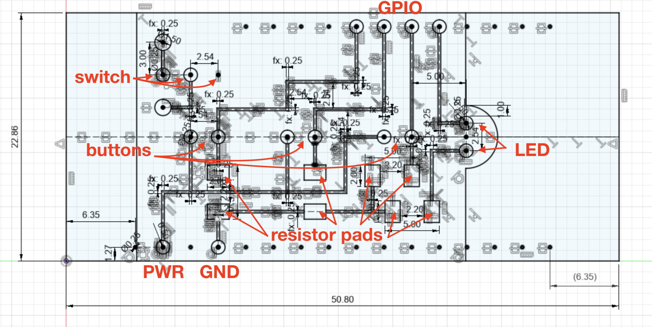
The final sketch. Look at all those constraints!
In order to achieve a small footprint, I decided to mount the PCB right onto the Feather pins, similar to how it plugs into a breadboard. I found the dimensions for the Feather's pins on Adafruit's website, then decided what the rest of the board would look like.
Based on my two lists, I knew I needed at least two buttons and an on/off switch at minimum. I wanted to be able to really conserve power with the on/off switch, so ideally the chip wasn't constantly listening for whether the switch had been flipped back on. As such, the switch would go between the battery and the microcontroller.
I also decided on three buttons total in a line along the middle of the PCB. The top button is volume up, the middle button is push to talk, and the bottom button is volume down. Clicking both top and bottom buttons at the same time is play/pause, letting me add a Neat list item.
I struggled to figure out how to wire the buttons. Since each button needed to be connected to power, ground, and a GPIO pin, I couldn't figure out how to do it without crossing traces. I asked on Slack about double-sided PCBs, but Nathan provided a better solution. He mentioned using 0 Ohm resistors as bridges, but since the Feather doesn't have built-in pullup resistors, I needed to put a resistor on each button anyway! Using those as a bridge, I figured out a wiring path that doesn't cross any traces. The rectangular pads are for mounting the resistors. The four bottom right pads are for two horizontal resistors, and the four bottom left pads are for two vertical resistors.
I had a little bit of extra space, so I figured I'd add in an LED. It's the simple one color version, since I didn't have space for three whole resistors required to add a multicolor LED, and it's at the end of the line of buttons.
With the PCB designed and myself thoroughly in isolation, I asked Nathan if he could mill it for me. This is when I realized that I should have used Eagle to create the schematic rather than the safe familiarity of normal Fusion360- there wasn't a good way to export the files. The 2.5D mill takes PNG images, and I am able to capture a high-quality screenshot; however, in order to make sure the dimensions are correct (which is important so that it fits on the microcontroller), I had to export an image with the correct dimensions at 1000 dpi. Photoshop helped.


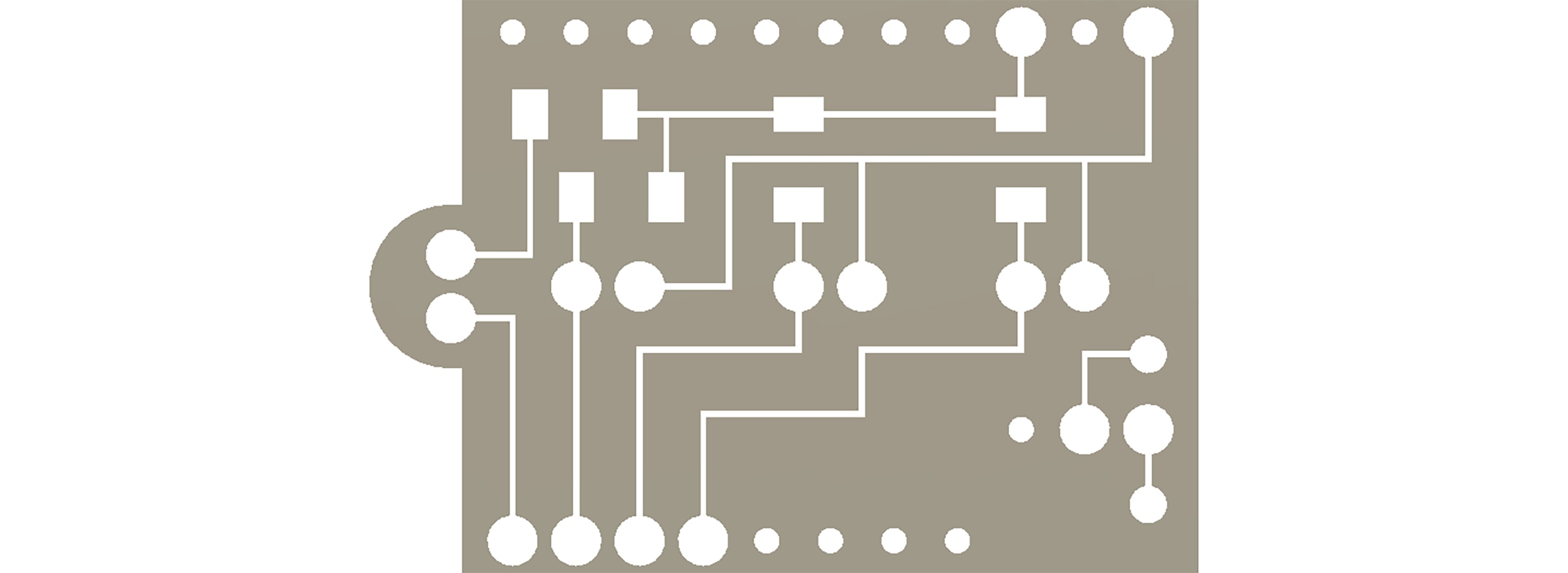
The final images; first, the traces to engrave, then the holes to drill out.


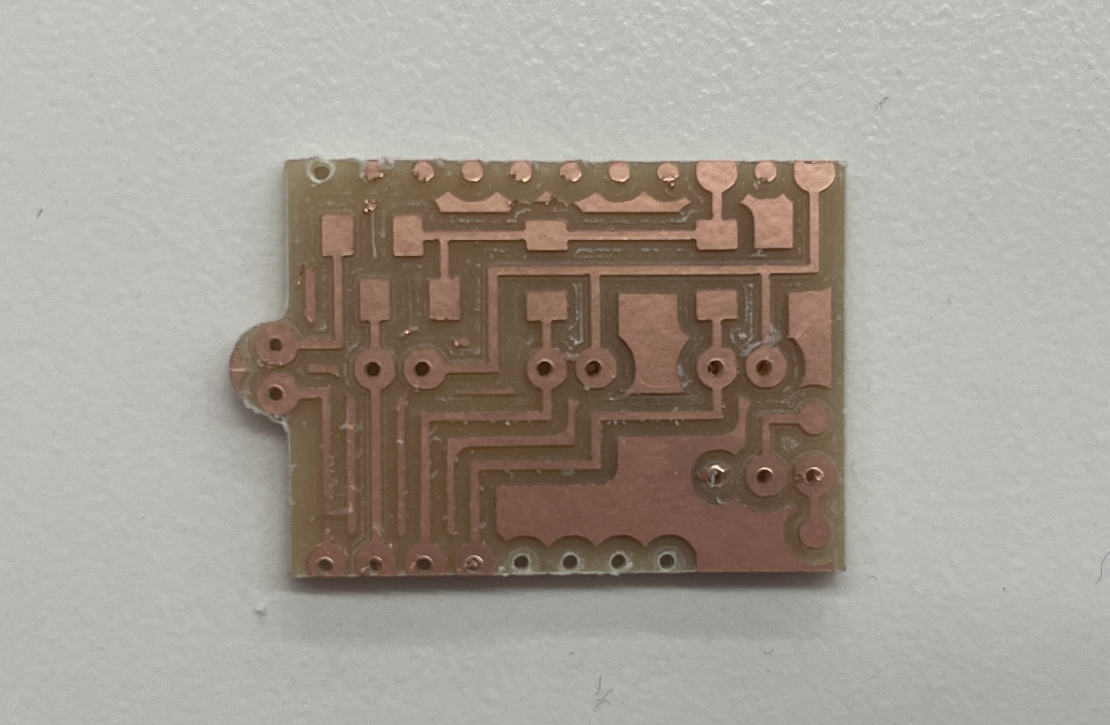
The traces look great! And some of the holes!
Unfortunately, the mill cut the outline before finishing all of the holes, and the piece flew out. Fortunately, most of the important holes were already done, so I could simply drill out the other holes. I am, however, not nearly as precise as a milling machine, so my holes are a bit messier.
Once I drilled out the remaining holes, I dry-fit all of the components together. This is when I realized that I did not have the correct dimensions for the buttons. I made the space between their leads too small, making it such that the buttons cannot lie flat on the board. I really wish they did lie flat, but since I don't have enough time to cut another board, this'll do.

check out that sick bend
I'm cheating a bit, since that image is actually from after I soldered these components on. If you look closely, you can see the beads on the underside of the board. But even if the buttons don't quite fit the way I wish they would, they're still attached. This board has a switch, LED, and three buttons. All it needs now is a battery connection and attachment to the microcontroller.
Unfortunately, due to the time constraints of isolation and my flight back home, I didn't get to attach the lipo battery as I intended. I wanted to cut one of the leads, solder the switch into it, and then plug it into the Feather. That way, the switch would manually control whether the microcontroller had power or not. Fortunately, I do have a USB power bank, so I can still operate the device remotely from my computer - it's just a little bit bulkier.

The PCB soldered to the microcontroller. It's attached via solder on ground, power, and four GPIO pins.
With the physical construction done - or at least as done as it could be - I moved on to code. I referenced my code from Week 11 and the Blink Without Delay example.
#include <BleKeyboard.h>
BleKeyboard bleKeyboard;

int buttonPins[] = {12, 27, 33};
int buttonPrevMillis = 0;
int buttonDelay = 100;
int ledPin = 15;

bool pushing = false;
// ledCode: 0 is off, 1 is flashing quickly for BLE search,
// 2 is mild pulse for on, 3 is bright for pushing to talk
int ledCode = 0;
float ledState = 255;
unsigned long previousMillis = 0;
int ledSlowBlink = 2500;
int ledFastBlink = 200;

void setup() {
  Serial.begin(115200);
  Serial.println("Starting BLE work!");
  bleKeyboard.setName("PK's BLE Controller");
  bleKeyboard.begin();

  for (int i = 0; i < 3; i++) {
    pinMode(buttonPins[i], INPUT);
  }
  analogWrite(ledPin, 20);
}


void loop() {
  unsigned long currentMillis = millis();
  if (bleKeyboard.isConnected()) {
    // if there hasn't just been a button press
    if (currentMillis - buttonPrevMillis >= buttonDelay) {
      ledCode = 2;
      buttonPrevMillis = currentMillis;

      // volume up/down buttons and play/pause if both are pushed
      if (digitalRead(buttonPins[0])) {
        if (digitalRead(buttonPins[2])) {
          bleKeyboard.write(KEY_MEDIA_PLAY_PAUSE);
        } else {
          bleKeyboard.write(KEY_MEDIA_VOLUME_UP);
        }
      } else if (digitalRead(buttonPins[2])) {
        bleKeyboard.write(KEY_MEDIA_VOLUME_DOWN);
      }

      // simulate a control-alt-command keypress because i can't find any other program that uses that as a command
      // anything with a PTT system lets you configure which key it is
      // so this works :)
      // pushing variable makes sure press() and releaseAll() are only called once per PTT
      if (digitalRead(buttonPins[1])) {
        ledCode = 3;
        if (not pushing) {
          bleKeyboard.press(KEY_LEFT_CTRL);
          bleKeyboard.press(KEY_LEFT_ALT);
          bleKeyboard.press(KEY_LEFT_GUI);
          pushing = true;
        }
      } else if (pushing) {
        bleKeyboard.releaseAll();
        pushing = false;
      }
    }

  } else {
    ledCode = 1;
  }

  // LED control

  if (ledCode == 1 and currentMillis - previousMillis >= ledFastBlink) {
    if (ledState == 0) {
      ledState = 20;
    } else {
      ledState = 0;
      Serial.println("ESP32 not connected! check your BLE");
    }
    previousMillis = currentMillis;

  } else if (ledCode == 2) {
    float maxBright = 5.0;
    if (currentMillis - previousMillis >= 2*ledSlowBlink) {
      previousMillis = currentMillis;
    } else if (currentMillis - previousMillis >= ledSlowBlink) {
      // scale it so that it blinks over the duration of ledSlowBlink
      // (x - in_min) * (out_max - out_min) / (in_max - in_min) + out_min;
      ledState = (currentMillis - previousMillis - ledSlowBlink) * maxBright / ledSlowBlink;
    } else {
      ledState = maxBright - (currentMillis - previousMillis) * maxBright / ledSlowBlink;
    }
    ledState = constrain(ledState, 0, maxBright);

  } else if (ledCode == 3) {
    ledState = 255;
  }

  analogWrite(ledPin, ledState);
  delay(10);
}
fyi- below this is the same content as the Showcase section above if you've already seen that
First to showcase are the buttons- top button for volume up, bottom button for volume down, middle button for push to talk, and both volumes for play/pause.
featuring my excellent music taste.
The first video shows the volume controls. For the push to talk video, this is on a Discord call, so the green circle indicates that it's receiving the push-to-talk signal. The last video has the Spotify play bar at the bottom of the screen so you can see that it's actually playing/pausing. I think this is the weakest part of the project- it's really difficult to not also adjust the volume, and requires two hands. But hey, this's why we make prototypes.
Next is the indicator light. It flashes quickly while searching for a Bluetooth connection, blinks slowly when on, and holds bright when push to talk is active. (I changed how I wanted the LED to work after I filmed the button videos so there is a slight lack of consistency there, sorry~!)
The first video shows the quick flash searching indicator. The second video is the slow blink - it looks less but still a little bit choppy in real life. The stepping is due to the board's PWM only accepting integer values. The last video is the brightness when you hold down the push to talk button. I will never accidentally push it without realizing and then say something embarassing, which is a core fear of mine, because this light is very bright.