Electronic Outputs
1. Use an output device that you haven't used before.
2. Write a microcontroller program that integrates at least one input device and one output device. Avoid the delay() function by using either timers or interrupts.
3. Use an oscilloscope to discover the time domain at which your output device is operating. Is it on a fixed clock? What's its speed? Share images and describe your findings.
4. Prepare CAD files for CNC week (after spring break). Consider either 2D DXF files for routing sheet material (like plywood or OSB), or 3D STL files to mill out a (2.5D) shape. We will also cover molding & casting, so you may want to consider milling a mold.
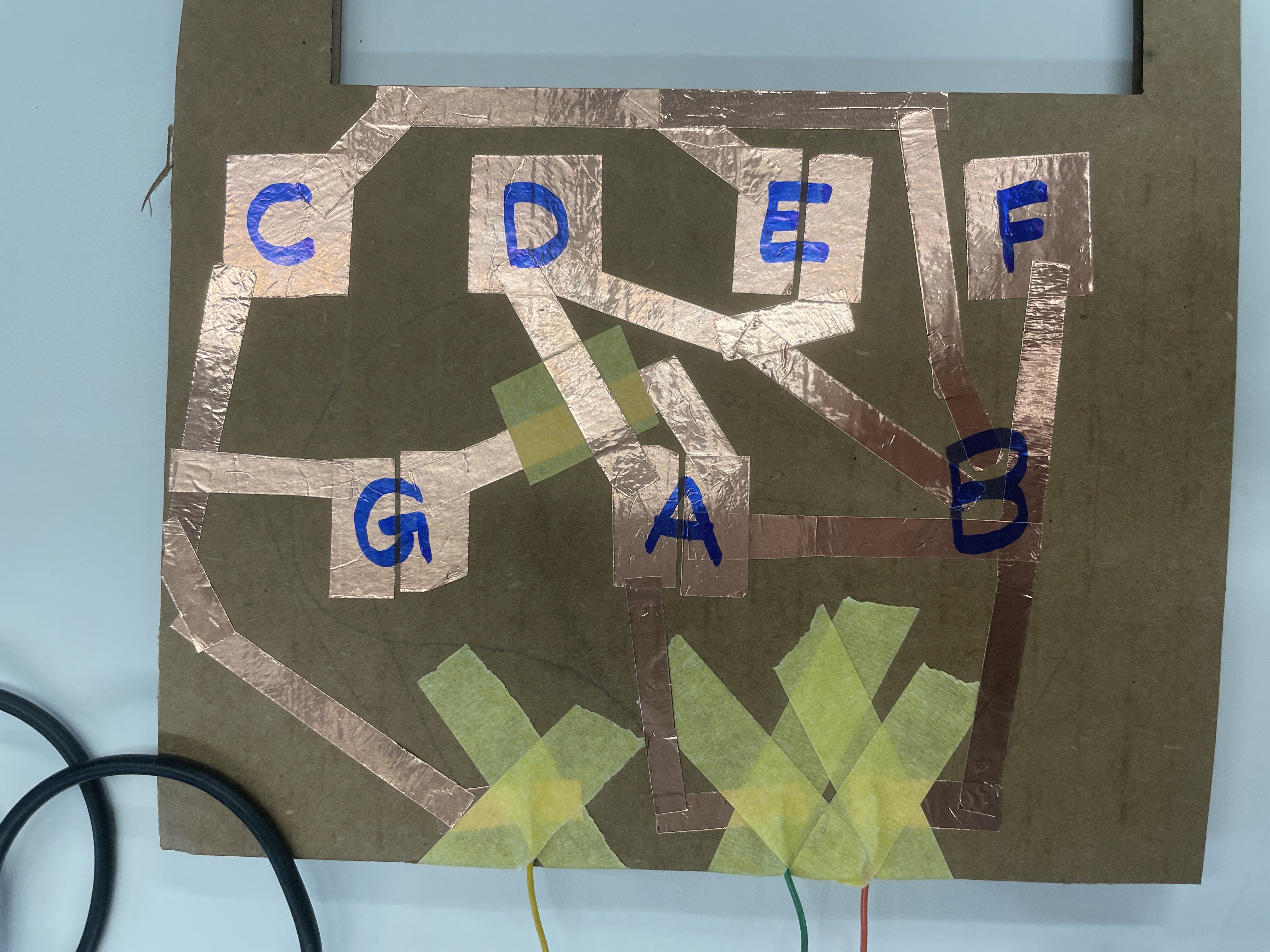
For this week, I learned how to use a piezzo buzzer as an output device. I wanted to make a device that lets you play different notes. Initially, I used buttons on a breadboard, but realized that I didn't like the button size and closeness mandated by the breadboard. I decided to get rid of the buttons and instead make my own, larger buttons with copper tape. I wanted to try to minimize the number of pins needed, so instead of having a circuit for each note, I used 3 pins together. To make the note play, you touch some combination of the pins to a copper pad connected to ground. To fulfill the no-delay() requirement, the piano beeps if you hold the keys.
Beeping piano!
With three pins that can either be high or low, there are 2^3 or 8 total configurations. I mapped the pins such that the yellow wire in pin 4 is the 1s place, the green wire in pin 3 is the 2s place, and the red wire in pin 2 is the 4s place. I used Arduino's built-in pullup resistor on these three pins so that they normally read HIGH, unless they were in contact with ground, in which case they read LOW.

"Wiring" of the piano keys, and a more organized diagram made with www.circuit-diagram.org. The yellow tape between D and A is a bridge to isolate the overlapping paths.
Here's my code:
int buzzerPin = 10;
// hertz for c major scale
int notes[] = {262, 294, 330, 349, 392, 440, 494};

// timer variables
long previousMillis = 0;
// see later
long interval = 0;
// bopping represents whether the tone is on or off
// when no contact, it's false
// when contact, it alternates
bool bopping = false;

void setup() {

  pinMode(2, INPUT_PULLUP);
  pinMode(3, INPUT_PULLUP);
  pinMode(4, INPUT_PULLUP);

}

void loop() {
  // input: check the pins
  // because i'm using the internal pullup, digitalRead() returns 1 for not touching and 0 for touching
  // but that makes my math hard later so i switched it here
  int pin2 = - (digitalRead(2) - 1); // 0 is not touching, 1 is touching
  int pin3 = - (digitalRead(3) - 1);
  int pin4 = - (digitalRead(4) - 1);

  // binary to decimal conversion
  int value = pin4 + pin3 * 2 + pin2 * 4; // 0 is none touching, 7 is all touching

  // if a note is being pressed
  if (value != 0) {
    // start the timer
    unsigned long currentMillis = millis();

    // if this is a new contact, then interval = 0 (via initialization or the else below)
    // therefore this if will pass
    // if this is not a new contact, then interval = 500
    // and it will work like a timer
    if (currentMillis - previousMillis >= interval) {
      previousMillis = currentMillis;
      interval = 500;
      // switch whether the tone is on or not
      bopping = not bopping;
    }

  } else {
    // reset
    interval = 0;
    bopping = false;
  }

  if (bopping) {
    tone(buzzerPin, notes[value - 1]);
  } else {
    noTone(buzzerPin);
  }
}
fun fact: the arduino editor has a right-click option "Copy as HTML" which makes these pretty colors!
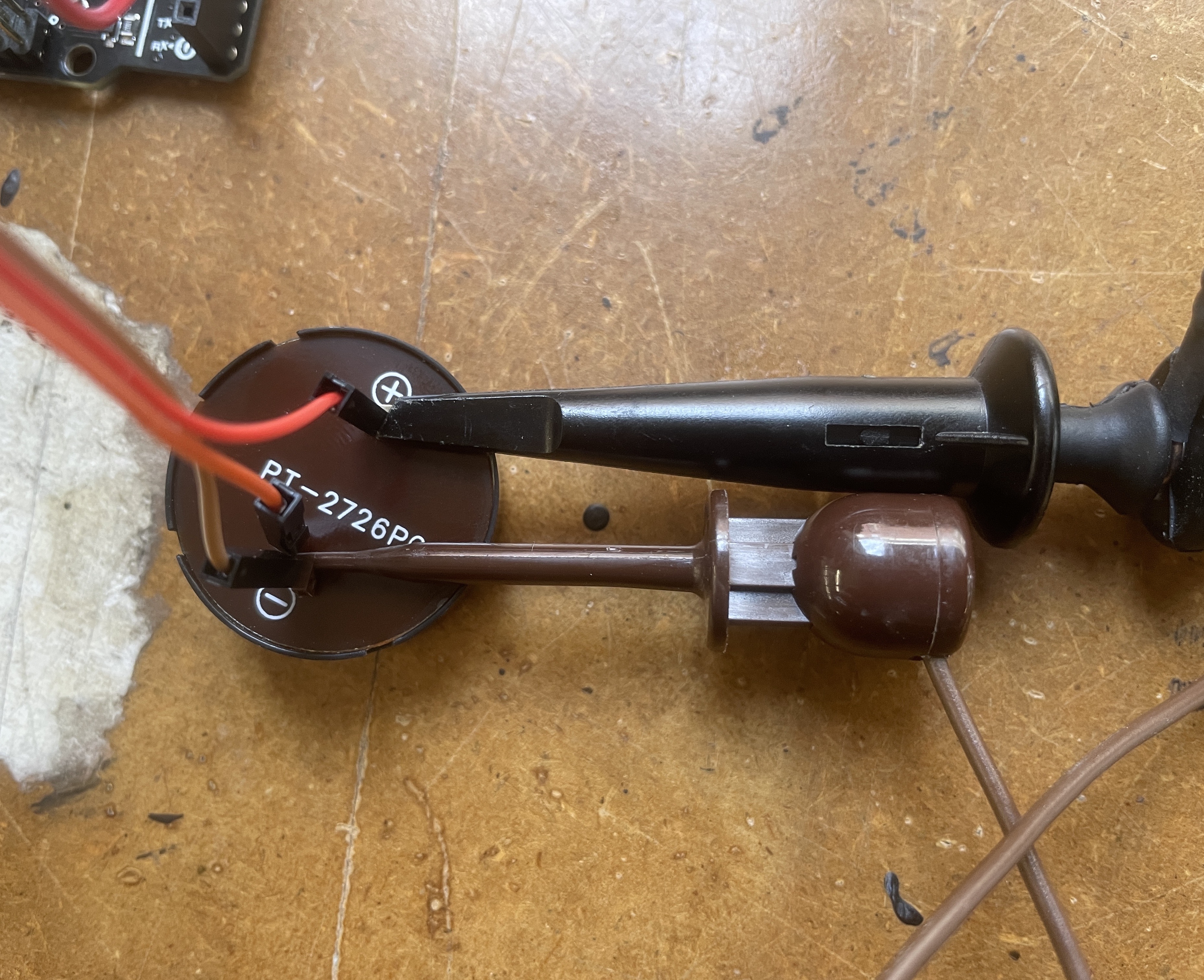
Getting the oscilloscope to work was difficult. I followed the tutorial from the course site and a conglomeration of images and tutorials from googling "oscilloscope." Eventually, I got some results - when the sound was playing, a line showed up on the screen. Since the beeps were so short in duration, the oscope was having difficulty automatically scaling itself.
beep.. beep.. beep..
In order to determine the clock speed, I messed around with the settings until I got a consistent square wave. The bottom-right corner consistently read 262.797 Hz when playing the lowest beep. If you look at my code, the lowest beep is intended at 262 Hz. The pattern continued for the other notes, where the measured Hz on the oscilloscope matched the programmed tone.


Oscilloscope reading and placement of the oscilloscope probes on the signal and ground of the buzzer.