Kinetic Sculpture
Create a kinetic sculpture. Include circuitry to move your sculpture. Control the sculpture with a circuit on a breadboard that uses components in the lab (e.g., resistors, potentiometer). Use a multimeter to measure the voltages in your circuit. Use Ohm's law to calculate current through the circuit.
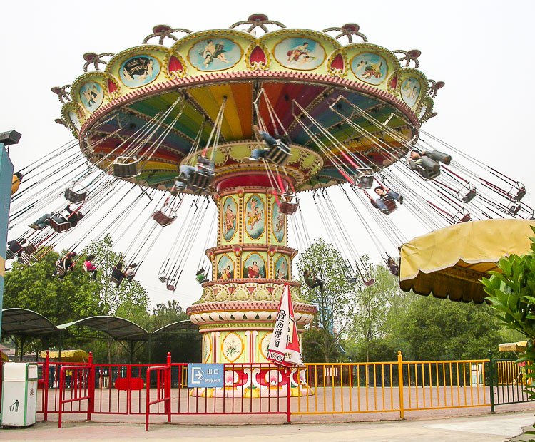
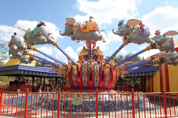
When thinking about what sort of kinetic sculpture I wanted to make, I was inspired by an amusement park ride I used to like when I was younger, which Google says is called an "aerial carousel." I also liked the Disneyland Dumbo ride, which is similar movement for the rider but a different mechanical attachment. I roughly drew from these mechanical motions when designing my sculpture.
I started with some rough sketches of the movement I wanted. I knew that I could get rotation from the yellow motors we soldered in class, so I started from there. I made a tester piece to check my kerf and figure out how best to attach plywood to the motor shaft. I figured out that a circle with a radius of 5.4mm and flat sides 3.7mm apart made a tight but not too tight press-fit.
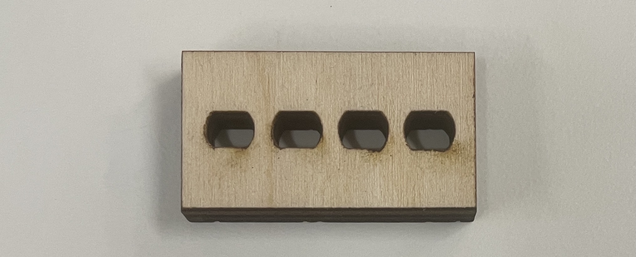
If they all look the same, it's because each cutout is varied by only 0.1mm.
Next was making gears. I used a Fusion extension called GF Gear Generator to model them. It asked me for a bunch of parameters, which I didn't understand, so I made a whole bunch of weird and wrong gears in order to understand how each parameter changed the outputted gear. I learned that the pitch diameter of the gear = the module * the number of teeth. Once I figured that out, I made three gears: an outer ring and two sizes of spur gears.
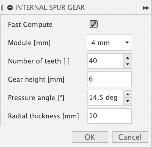
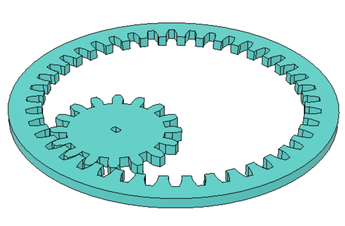
the gear generator options menu, and the outer ring with one of the spur gears.
Once I laser cut the gears, it was time for assembly. The motor fit the spur gear, and the spur gear fit the ring gear - when it was properly spaced. I was holding the motor in place to test and couldn't hold it perfectly still. When the gears were too far apart, the outer ring wouldn't spin. When the gears were too close together, the motor was not strong enough to keep going, and both gears would stop spinning. Both of these options were not good, so I needed to find a way to keep the spacing consistent. I decided to make a base plate with a cutout for the motor so that it would stay in one spot. Then, in order to keep the ring gear in the right position, I constrained it with three little circles attached to the base plate.
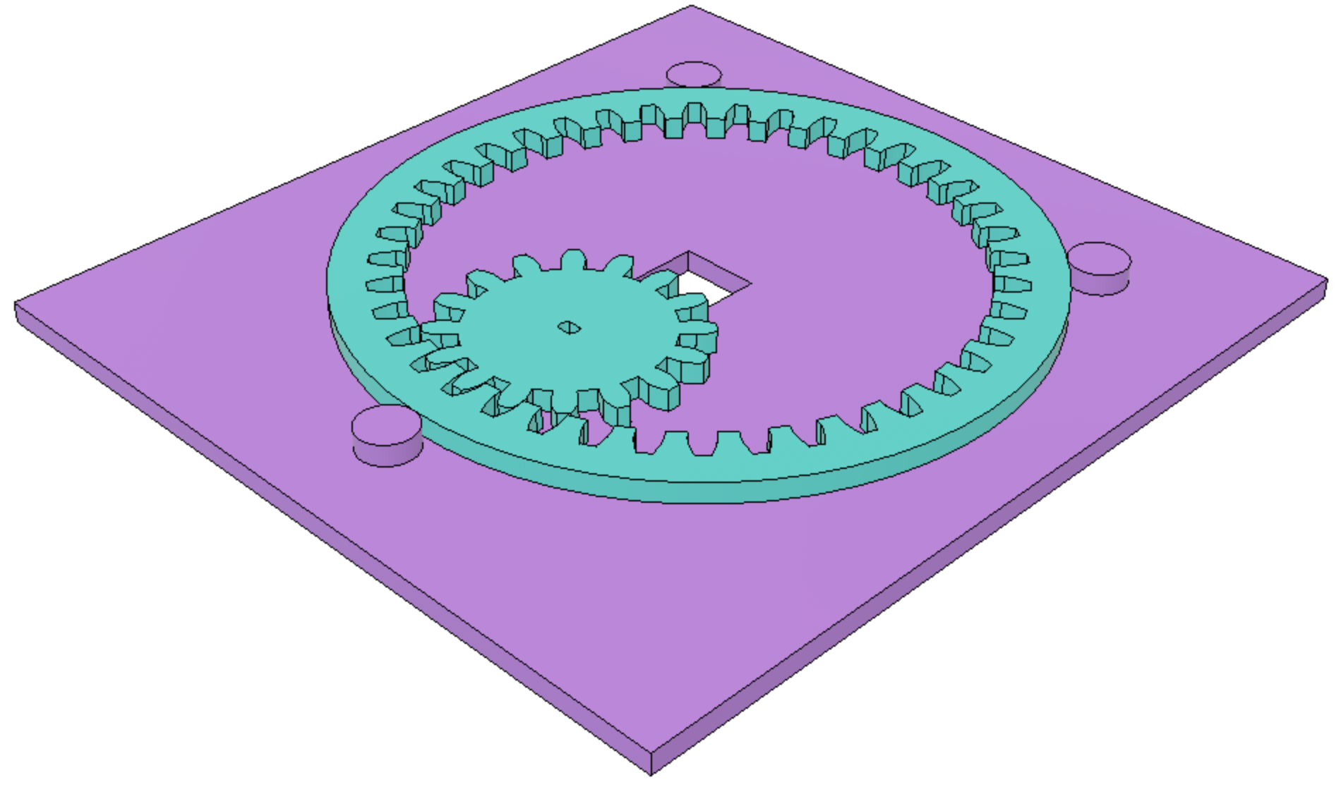
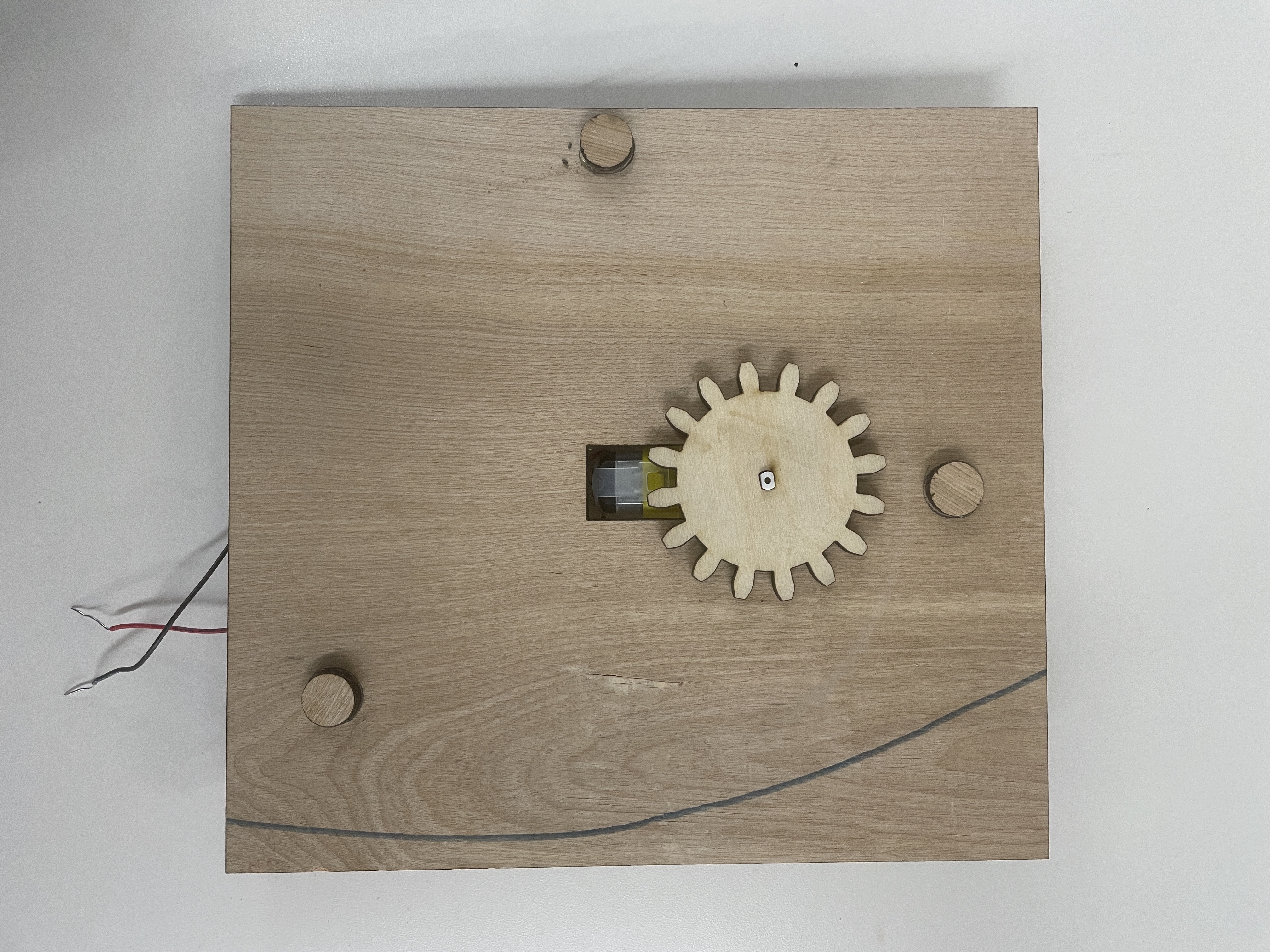
the base plate with the gears in fusion and the base plate once constructed.
After carefully aligning the tiny circles to keep everything in place, I tested it and it worked! But it wasn't the amusement park ride I was hoping for, so I needed to decorate the spinning ring. I explored the lab for interesting materials, and found some thin hollow metal tubing, wooden beads in a bin labelled "toy parts," and string.
it works! here's normal speed and then slowmo...
For the next part of the assignment, I had to measure the voltage and resistance and determine the current running through the circuit. Since I wanted the motor to spin quickly, I didn't put any resistors in my breadboard and used the 5V power from my Arduino. Ohm's law states that V=IR, where V is the voltage in volts, I is the current in amps, and R is the resistance in ohms. I measured 5.1 V and 4.9 ohms. I=V/R so the current running through the circuit was 1.04 A.